|
Capacitor type
|
Dielectric used
|
Features/applications
|
Disadvantages
|
|
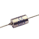
Paper Capacitors
|
Paper or oil-impregnated paper
|
Impregnated paper was extensively used for older capacitors, using wax, oil, or epoxy as an impregnate. Oil-Kraft paper capacitors are still used in certain high voltage applications. Has mostly been replaced by plastic film capacitors.
|
Large size. Also, paper is highly hygroscopic, absorbing moisture from the atmosphere despite plastic enclosures and impregnates. Absorbed moisture degrades performance by increasing dielectric losses (power factor) and decreasing insulation resistance.
|
|
Metalized Paper Capacitors
|
Paper
|
Comparatively smaller in size than paper-foil capacitors
|
Suitable only for lower current applications. Has been largely superseded by metalized film capacitors
|
|
PET film Capacitor
|
Polyester film
|
Smaller in size when compared to paper or polypropylene capacitors of comparable specifications. May use plates of foil, metalized film, or a combination. PET film capacitors have almost completely replaced paper capacitors for most DC electronic applications. Operating voltages up to 60,000 V DC and operating temperatures up to 125 °C. Low moisture absorption.
|
Temperature stability is poorer than paper capacitors. Usable at low (AC power) frequencies, but inappropriate for RF applications due to excessive dielectric heating.
|
|
Kapton Capacitor
|
Kapton polyimide film
|
Similar to PET film, but significantly higher operating temperature (up to 250 °C).
|
Higher cost than PET. Temperature stability is poorer than paper capacitors. Usable at low (AC power) frequencies, but inappropriate for RF applications due to excessive dielectric heating.
|
|
Polystyrene Capacitor
|
Polystyrene
|
Excellent general purpose plastic film capacitor. Excellent stability, low moisture pick-up and a slightly negative temperature coefficient that can be used to match the positive temperature co-efficient of other components. Ideal for low power RF and precision analog applications
|
Maximum operating temperature is limited to about +85 °C. Comparatively bigger in size.
|
|
Polycarbonate Plastic Film Capacitor
|
Polycarbonate
|
Superior insulation resistance, dissipation factor, and dielectric absorption versus polystyrene capacitors. Moisture pick-up is less, with about ±80 ppm temperature coefficient. Can use full operating voltage across entire temperature range (−55 °C to 125 °C)
|
Maximum operating temperature limited to about 125 °C.
|
|
Polypropylene Plastic Film Capacitors
|
Polypropylene
|
Has become the most popular capacitor dielectric [citation needed]. Extremely low dissipation factor, higher dielectric strength than polycarbonate and polyester films, low moisture absorption, and high insulation resistance. May use plates of foil, metalized film, or a combination. Film is compatible with self-healing technology to improve reliability. Usable in high frequency applications due to very low dielectric losses. Larger value and higher voltage types from 1 to 100 μF at up to 440 V AC are used as run capacitors in some types of single phase electric motors.
|
More susceptible to damage from transient over-voltages or voltage reversals than oil-impregnated Kraft paper for pulsed power energy discharge applications.
|
|
Polysulphone Plastic Film Capacitors
|
Polysulfone
|
Similar to polycarbonate. Can withstand full voltage at comparatively higher temperatures. Moisture pick-up is typically 0.2%, limiting its stability.
|
Very limited availability and higher cost
|
|
PTFE Fluorocarbon (TEFLON) Film Capacitors
|
Polytetra- fluoroethylene
|
Lowest loss solid dielectric. Operating temperatures up to 250 °C, extremely high insulation resistance, and good stability. Used in stringent, mission-critical applications
|
Large size (due to low dielectric constant), and higher cost than other film capacitors.
|
|
Polyamide Plastic Film Capacitors
|
Polyamide
|
Operating temperatures of up to 200 °C. High insulation resistance, good stability and low dissipation factor.
|
Large size and high cost.
|
|
Metalized Plastic Film Capacitors
|
Polyester or Polycarbonate
|
Reliable and significantly smaller in size. Thin metallization can be used to advantage by making capacitors "self healing".
|
Thin plates limit maximum current carrying capability.
|
|
Stacked Plate Mica Capacitors
|
Mica
|
Advantages of mica capacitors arise from the fact that the dielectric material (mica) is inert. It does not change physically or chemically with age and it has good temperature stability. Very resistant to corona damage
|
Unless properly sealed, susceptible to moisture pick-up which will increase the power factor and decrease insulation resistance. Higher cost due to scarcity of high grade dielectric material and manually-intensive assembly.
|
|
Metalized Mica or Silver Mica Capacitors
|
Mica
|
Silver mica capacitors have the above mentioned advantages. In addition, they have much reduced moisture infiltration.
|
Higher cost
|
|
Glass Capacitors
|
Glass
|
Similar to Mica Capacitors. Stability and frequency characteristics are better than silver mica capacitors. Ultra-reliable, ultra-stable, and resistant to nuclear radiation.
|
High cost.
|
|
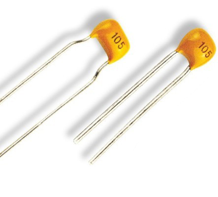
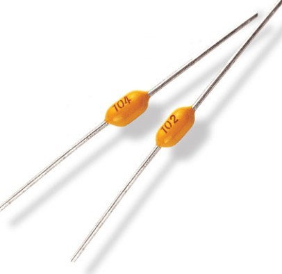
Class-I Temperature Compensating Type Ceramic Capacitors
|
Mixture of complex Titanate compounds
|
Low cost and small size, excellent high frequency characteristics and good reliability. Predictable linear capacitance change with operating temperature. Available in voltages up to 15,000 volts
|
Capacitance changes with change in applied voltage, with frequency and with aging effects.
|
|
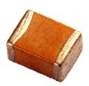
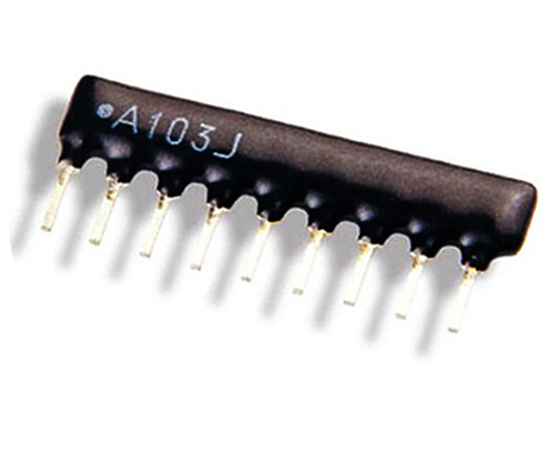
Class-II High dielectric strength Type Ceramic Capacitors
|
Barium titanate based dielectrics
|
Smaller than Class-I type due to higher dielectric strength of ceramics used. Available in voltages up to 50,000 volts.
|
Not as stable as Class-I type with respect to temperature, and capacitance changes significantly with applied voltage.
|
|
Aluminum Electrolytic Capacitors
|
Aluminum oxide
|
Very large capacitance to volume ratio, inexpensive, polarized. Primary applications are as smoothing and reservoir capacitors in power supplies.
|
Dielectric leakage is high, large internal resistance and inductance limits high frequency performance, poor low temperature stability and loose tolerances. May vent or burst open when overloaded and/or overheated. Limited to about 500 volts.
|
|
Lithium Ion Capacitors
|
Lithium ion
|
The lithium ion capacitors have a higher power density as compared to batteries and LIC’s are safer in use than LIB’s in which thermal runaway reactions may occur. Compared to electric double layer capacitor (EDLC), the LIC has a higher output voltage. They both have similar power densities, but energy density of an LIC is much higher.
|
New technology.
|
|
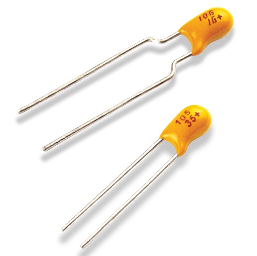
Tantalum Electrolytic Capacitors
|
Tantalum oxide
|
Large capacitance to volume ratio, smaller size, good stability, wide operating temperature range, long reliable operating life. Extensively used in miniaturized equipment and computers. Available in both polarized and unpolarized varieties. Solid tantalum capacitors have much better characteristics than their wet counterparts.
|
Higher cost than aluminum electrolytic capacitors. Voltage limited to about 50 volts. Explodes quite violently when voltage rating, current rating, or slew rates are exceeded, or when a polarized version is subjected to reverse voltage.
|
|
Electrolytic double-layer capacitors (EDLC) Supercapacitors
|
Thin Electrolyte layer and Activated Carbon
|
Extremely large capacitance to volume ratio, small size, low ESR. Available in hundreds, or thousands, of farads. A relatively new capacitor technology. Often used to temporarily provide power to equipment during battery replacement. Can rapidly absorb and deliver larger currents than batteries during charging and discharging, making them valuable for hybrid vehicles. Polarized, low operating voltage (volts per capacitor cell). Groups of cells are stacked to provide higher overall operating voltage.
|
Relatively high cost.
|
|
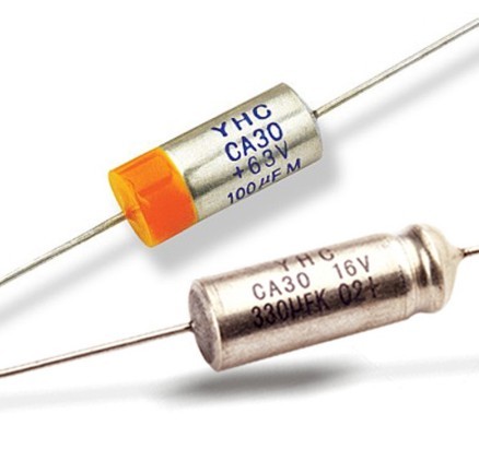
Alternating current oil-filled Capacitors
|
Oil-impregnated paper
|
Usually PET or polypropylene film dielectric. Primarily designed to provide very large capacitance for industrial AC applications to withstand large currents and high peak voltages at power line frequencies. The applications include AC motor starting and running, phase splitting, power factor correction, voltage regulation, control equipment, etc..
|
Limited to low frequency applications due to high dielectric losses at higher frequencies.
|
|
Direct current oil-filled capacitors
|
Paper or Paper-polyester film combination
|
Primarily designed for DC applications such as filtering, bypassing, coupling, arc suppression, voltage doubling, etc...
|
Operating voltage rating must be derated as per the curve supplied by the manufacturer if the DC contains ripple. Physically larger than polymer dielectric counterparts.
|
|
Energy Storage Capacitors
|
Kraft capacitor paper impregnated with electrical grade castor oil or similar high dielectric constant fluid, with extended foil plates
|
Designed specifically for intermittent duty, high current discharge applications. More tolerant of voltage reversal than many polymer dielectrics. Typical applications include pulsed power, electromagnetic forming, pulsed lasers, Marx generators, and pulsed welders.
|
Physically large and heavy. Significantly lower energy density than polymer dielectric systems. Not self-healing. Device may fail catastrophically due to high stored energy.
|
|
Vacuum Capacitors
|
Vacuum capacitors use highly evacuated glass or ceramic chamber with concentric cylindrical electrodes.
|
Extremely low loss. Used for high voltage high power RF applications, such as transmitters and induction heating where even a small amount of dielectric loss would cause excessive heating. Can be self-healing if arc-over current is limited.
|
Very high cost, fragile, physically large, and relatively low capacitance.
|