Product specification: CA45 Specifications-19-06-03.pdf
>>Features
Solid tantalum chip capacitors are designed and manufactured with the demanding requirements of surface mount technology in mind. There are A, B, C, D, E, S six case available. Chip tantalum capacitors have lower ESR comparing with the dipped tantalum capacitors .This product is compatible with automatic pick and place equipment. Suitable for military equipment and computer 、mobile phone and other electronic products. It meets the requirements of EIA 535BAAC and QC300801 、Q/YHC 45-01 standard.

>>General Characteristics
◆ Operating temperature: -55℃ ~ +125℃ (above 85℃, use dreaded voltage).
◆ Capacitance Tolerance: ±20%,±10% .
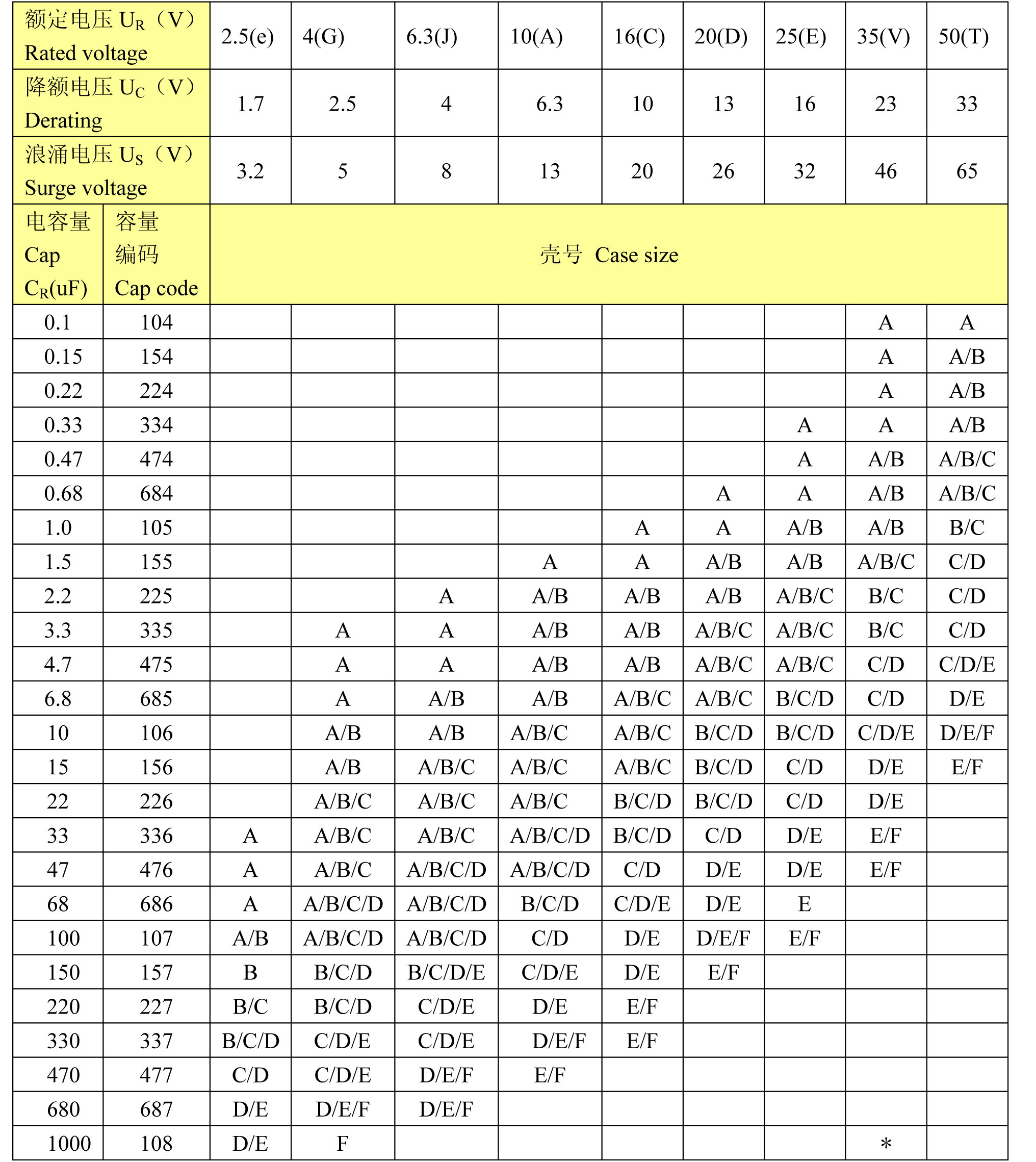
◆ Capacitance Range: 0.1μF~1000μF.
◆ Voltage Rating:2.5V~50V.
◆ DC leakage current(20):I0 ≤0.01CRUR or 0.5μA (whichever is greater ) .
◆ Dissipation factor (20℃): see table 1.
◆ Temperature performance: see table 1.
◆ Climatic category: 55/125/21.
◆ Life test: 2000 hours.
◆ Reliability:2% per 1000h at 85℃ with 0.1Ω/V series impedance 60% confidence level.
Table1

>>Drawing And Dimension


>>Rating and Case Code
>>Marking Specification

>>Carrier Tape Dimension


>>Reel Dimensions

>>How To Order
(CA45 106 M 035 D T)

>> Rating And Part Number Performance
Rated Voltage, Voltage Derating, Surge Voltage and Nominal Capacitance

ESR value of capacitors

>> Component Characteristics
>>Capacitance
Capacitance is measured at 120HZ,less than 1.0 volts rms, at 25℃ Capacitance increases with increasing temperature.
DC leakage current (DCL)
DC leakage current is the current that ,after a five minute charging period , flows through a capacitor when voltage is measured at 25℃ with full rated DC voltage applied to the capacitor through a 1000 ohm resistor in series with the capacitor. DC current increases with increasing temperature.
Dissipation factor ( DF)
Dissipation factor is measured at 120HZ up to 1.0 volt rms maximum. DF increases with increasing frequency.
Temperature stability
| Step NO. | TEMP. | CAPACITANCE | DCL | DF |
| 1 | +25℃ | Within specified tolerance | Within original limit | Within original limit |
| 2 | -55℃ | Within ±10% initial value | N/A | Within original limit |
| 3 | +25℃ | Within ±5% initial value | Within original limit | Within original limit |
| 4 | +85℃ | Within ±10% initial value | Within10X original limit | See table 1 |
| 5 | +125℃ | Within ±12% initial value | Within12X original limit | See table 1 |
| 6 | +25℃ | Within ±5% initial value | Within original limit | Within original limit |
Temperature cycle
-55 ℃,room temperature,125℃ ,5 cycles 30min , Post test performance:
a. Capacitance---within±5% initial value
b. DC Leakage---within initial limit
c. DF--- within initial limit
Life test
85℃,1.15 rated voltage measurement is done after 1000 cycles of 0.5 minutes on 5.5 minutes off with 1000 Ω of series resistance. Post test performance:
a. Capacitance---within ±10% initial value
b. Leakage---within initial limit
c. DF--- within initial limit
Solvent resistance
Solution: isopropyl alcohol, solution temp:20-25℃ .The specimen shall be completely immersed in the solution for 1 min. and the marking shall be rubbed with a brush 10 times. The above cycle will be applied 3 times and then the marking shall be examined visually. post test performance:
a. Capacitance---within initial limit
b. DC Leakage---within initial limit
c. DF--- within initial limit
d. physical---Marking must be legible
Solder ability
Solder temperature:230±5℃,immersion times (solder):3±0.5sec, Immersion in flux 5-10sec, .The specimen shall be immersed completely, post test performance: The dipped portion of the termination is at least 95% covered by a new solder coating.
